A simple 3-way switch wiring diagram is essential for controlling a light from two different locations. Whether you’re installing new switches or troubleshooting an existing setup, this guide provides a detailed, easy-to-follow breakdown.
🔧 How a Simple 3-Way Switch Wiring Diagram Works
A simple 3-way switch wiring diagram allows you to control a single light fixture from two separate switches. This setup is common in hallways, staircases, and large rooms.
Key Components of a 3-Way Switch Circuit
| Component | Purpose |
|---|---|
| 3-Way Switches | Two switches control one light (no “on/off” markings). |
| Traveler Wires | Two wires (usually red & black) connect the switches. |
| Common Terminal | The third screw (usually darker) connects to power or light. |
| Neutral Wires | White wires complete the circuit (not always in switch boxes). |
| Ground Wires | Bare or green wires for safety. |
How Power Flows in a 3-Way Switch Setup
- Power enters at the first switch’s common terminal.
- Traveler wires carry current between switches.
- The second switch’s common terminal connects to the light.
- Flipping either switch breaks or completes the circuit.
⚡ Simple 3-Way Switch Wiring Diagram: Step-by-Step Setup
Follow this simple 3-way switch wiring diagram for a foolproof installation.
🔨 Tools & Materials Needed
- Two 3-way switches
- 14/3 or 12/3 NM cable (with black, red, white, ground)
- Wire strippers & screwdrivers
- Voltage tester
- Electrical tape & wire nuts
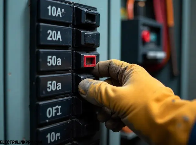
📌 Step 1: Turn Off Power
- Shut off the circuit at the breaker panel.
- Verify with a voltage tester.
📌 Step 2: Run Cable Between Switches
- Use 14/3 or 12/3 cable to connect both switches.
- The black & red wires are travelers.
- The white wire is neutral (may not be used in switch boxes).
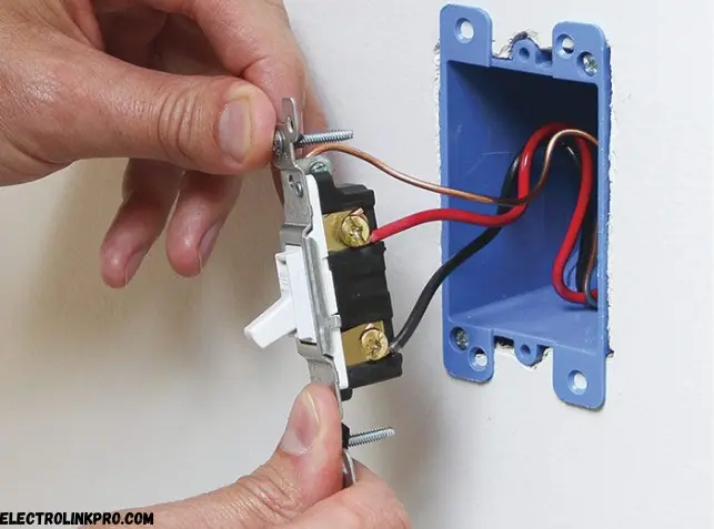
📌 Step 3: Connect the First 3-Way Switch
| Wire Color | Terminal |
|---|---|
| Black (Hot) | Common (dark screw) |
| Red & Black (Travelers) | Brass screws |
| Ground (Bare/Green) | Green screw |
📌 Step 4: Connect the Second 3-Way Switch
| Wire Color | Terminal |
|---|---|
| Black (to Light) | Common (dark screw) |
| Red & Black (Travelers) | Brass screws |
| Ground (Bare/Green) | Green screw |
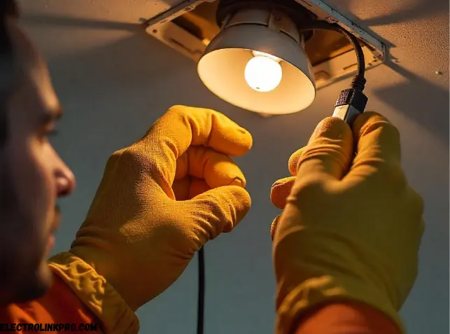
📌 Step 5: Test the Circuit
- Restore power and test both switches.
- If the light doesn’t work, check traveler wire connections.
🚨 Common Mistakes in a Simple 3-Way Switch Wiring Diagram
Avoid these errors for a safe, functional setup:
❌ Mixing Up Common & Traveler Wires
- The common terminal must connect to power or the light.
- Swapping travelers will prevent the circuit from working.
❌ Incorrect Grounding
- Always secure ground wires to green screws.
❌ Using 2-Wire Cable Instead of 3-Wire
- A 3-wire cable (with red, black, white) is mandatory.
❌ Not Testing Before Finalizing
- Verify connections with a voltage tester before closing the box.
🔍 Related Wiring Configurations
4-Way Switch Setup (3+ Switches)
- Adds extra switches between two 3-way switches.
Smart 3-Way Switches
- Requires neutral wires for Wi-Fi/automation.
Dimmer-Compatible 3-Way Wiring
- One switch must be a dimmer, the other a standard 3-way.
Conclusion:
Understanding and correctly implementing a simple 3-way switch wiring diagram is essential for anyone working with residential or commercial electrical systems. This setup allows you to control a single light fixture from two different locations, making it highly practical for staircases, hallways, and large rooms.
🔹 Key Takeaways from This Guide
- Proper Wiring Configuration
- The common terminal (usually the darker screw) must be correctly identified and connected to either the power source or the light fixture.
- The traveler wires (red and black) carry current between the two switches and must be securely connected to the brass screws.
- Safety First
- Always turn off power at the breaker before working on electrical wiring.
- Use a voltage tester to confirm that circuits are de-energized.
- Properly ground all switches to prevent electrical hazards.
- Avoiding Common Mistakes
- Never mix up traveler and common wires, as this will prevent the circuit from functioning.
- Always use 3-conductor cable (14/3 or 12/3) to ensure proper connections.
- Double-check all connections before restoring power.
- Testing & Troubleshooting
- If the light doesn’t turn on, recheck traveler wire connections.
- Ensure all wire nuts are tight and no bare wires are exposed.
- If issues persist, consult a licensed electrician.
🔹 Advanced Applications & Future Considerations
- Smart 3-Way Switches – Many modern smart switches require a neutral wire for automation compatibility.
- Dimmer Integration – Only one of the switches in a 3-way setup should be a dimmer to avoid conflicts.
- 4-Way Switch Expansion – If you need more than two control points, a 4-way switch can be added between two 3-way switches.
🔹 Final Recommendations
If unsure, consult a professional electrician to ensure safety and compliance with local codes.
Label wires during installation to avoid confusion.
Take photos of wiring before closing the electrical box for future reference.
❓ Frequently Asked Questions (FAQs)
1. Can I use a 3-way switch as a single-pole switch?
Yes, but only one traveler terminal will be used.
2. Why does my 3-way switch only work one way?
Check if traveler wires are reversed at one switch.
3. Do I need a neutral wire for a 3-way switch?
Traditional mechanical switches don’t need it, but smart switches do.
4. What’s the difference between a 3-way and 4-way switch?
A 4-way switch adds extra control points between two 3-way switches.
5. Can I install a dimmer on a 3-way circuit?
Yes, but only one switch should be a dimmer.\z
Here are verified, working official links for 3-way switch wiring:
Wiring Guides & Codes
- NEC Standards – nfpa.org/70
- OSHA Electrical Safety – osha.gov/electrical
DIY Tutorials
- Family Handyman – familyhandyman.com/3-way-switch
- This Old House – thisoldhouse.com/3-way-switch
Smart Switches
- Lutron Wiring – lutron.com/3-way-wiring
Safety
- ESFI Guide – esfi.org/3-way-switches