Installing a 3-way switch wiring diagram is essential for controlling a single light from two different locations. Whether you’re upgrading your home lighting or troubleshooting an existing setup, this guide provides a detailed, step-by-step process to ensure a safe and efficient installation.
📋 Components Needed for a 3-Way Switch Wiring Diagram
Before starting, gather these essential components:
| Component | Purpose |
|---|---|
| Two 3-way switches | Allow control from two locations |
| 14/2 or 12/2 NM cable | Carries power from the source |
| 14/3 or 12/3 NM cable | Connects switches (carries traveler wires) |
| Light fixture | The load being controlled |
| Electrical box | Houses switches and connections |
| Wire connectors | Secures wire connections |
| Screwdriver & voltage tester | For installation and safety checks |
🔧 Step-by-Step 3-Way Switch Wiring Diagram & Installation
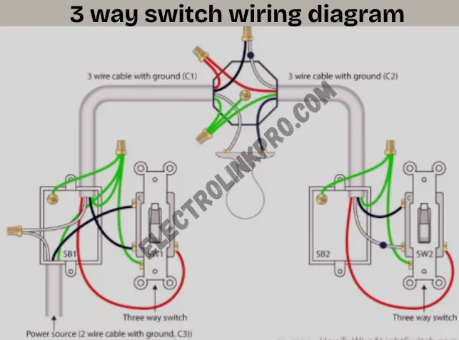
Wiring diagram for a 3 way switch wiring
1️⃣ Power Off & Safety Precautions
⚠️ Always turn off the circuit breaker before working on electrical wiring. Use a voltage tester to confirm power is off.
2️⃣ Identify Wiring Setup
A 3-way switch wiring diagram has two configurations:
- Power coming into the first switch
- Power coming into the light fixture
We’ll cover the most common setup (power at the first switch).
3️⃣ Connect the First 3-Way Switch
- Black (Hot) Wire → Connects to the common terminal (usually dark screw).
- White (Neutral) Wire → Pigtail with other neutrals (if needed).
- Red & Black (Traveler Wires) → Connect to the brass screws.
4️⃣ Run 3-Wire Cable Between Switches
- Use 14/3 or 12/3 cable to connect the two switches.
- Red & Black wires = Travelers (connect to brass screws).
- White wire = Neutral (not always used but must be capped if unused).
5️⃣ Connect the Second 3-Way Switch
- Black (Hot from light) → Connects to the common terminal.
- Red & Black (Travelers) → Connect to brass screws.
- Ground wires → Connect to green screws.
6️⃣ Wire the Light Fixture
- Black (Hot from switch) → Connects to the light.
- White (Neutral) → Connects to the neutral wire.
- Ground → Secured to the grounding terminal.
7️⃣ Test the Circuit
🔌 Turn power back on and test both switches to ensure proper operation.
⚡ Common 3-Way Switch Wiring Diagrams
| Wiring Configuration | Description |
|---|---|
| Power at Switch | Hot wire enters the first switch |
| Power at Light | Hot wire connects to the light first |
| Dead-End 3-Way | One switch has only travelers (no neutral) |
🚨 Troubleshooting a 3-Way Switch Wiring Diagram
❌ Lights not working? Check:
- Loose wire connections
- Incorrect traveler wire placement
- Faulty switches
💡 Pro Tip: Use a multimeter to test switch continuity.
🔍 Alternative Wiring Methods for a 3-Way Switch
- Smart 3-way switches (require neutral wire)
- 4-way switch additions (for controlling lights from 3+ locations)
Conclusion:
Installing a 3-way switch wiring diagram is an essential skill for homeowners and electricians alike. Whether you’re setting up a new lighting system or troubleshooting an existing one, understanding the correct wiring process ensures safe, efficient, and reliable operation.
🔑 Key Takeaways from This Guide
✅ Proper Planning is Crucial – Always start by identifying whether power enters at the first switch or the light fixture, as this determines your wiring approach.
✅ Correct Wire Connections Matter – Miswiring travelers or the common terminal is a common mistake that can prevent switches from working.
✅ Safety First – Always turn off power at the breaker and use a voltage tester before handling wires.
✅ Testing is Mandatory – After installation, verify that both switches control the light correctly before finalizing connections.
⚡ Why a 3-Way Switch Wiring Diagram is Useful
- Convenience: Control lights from two locations (e.g., top and bottom of stairs).
- Energy Efficiency: Avoid leaving lights on unnecessarily.
- Home Value: Properly installed switches improve functionality and safety.
🚀 Next Steps After Installation
✔ Label Your Switches – Helps future troubleshooting.
✔ Consider Smart Switches – Upgrade to Wi-Fi-enabled 3-way switches for remote control.
✔ Learn 4-Way Switch Wiring – Extend control to three or more locations.
⚠️ When to Call a Professional
While DIY installation is possible, consult a licensed electrician if:
- You encounter frequent tripping breakers.
- The wiring setup is unclear or outdated.
- You’re working with aluminum wiring (requires special handling).
🎯 Final Thoughts
By following this step-by-step 3-way switch wiring diagram guide, you can confidently install, troubleshoot, or upgrade your lighting system. Always double-check connections and adhere to electrical codes for a safe and long-lasting setup.
❓ Frequently Asked Questions (FAQs)
1. What is the purpose of a 3-way switch?
A 3-way switch wiring diagram allows control of a single light from two different locations.
2. Can I use a 3-way switch as a single-pole switch?
Yes, but you must cap the unused traveler wire.
3. Why is my 3-way switch not working?
Check for loose wires, incorrect traveler connections, or faulty switches.
4. Do all 3-way switches require a neutral wire?
Traditional 3-way switch wiring diagrams don’t always need a neutral, but smart switches do.
5. Can I add a 4-way switch to a 3-way setup?
Yes, a 4-way switch allows control from three or more locations.