A 3-way switch wiring schematic is essential for controlling a single light fixture from two different locations. Whether you’re upgrading your home lighting or troubleshooting an existing setup, understanding 3-way switch wiring schematics ensures safe and efficient electrical work.
This guide covers 3-way switch wiring schematics in full detail, including diagrams, step-by-step instructions, and pro tips. Let’s dive in! ⚡
📌 3-Way Switch Wiring Schematic: Key Components
Before wiring a 3-way switch schematic, you must know the essential parts:
| Component | Function |
|---|---|
| 3-Way Switches | Allow control from two locations |
| Traveler Wires | Carry current between switches (usually brass screws) |
| Common Terminal | Connects to the power source or light fixture (usually black screw) |
| Neutral Wires | Complete the circuit (usually white) |
| Ground Wires | Safety measure to prevent shocks (green or bare copper) |
🔧 How a 3-Way Switch Works
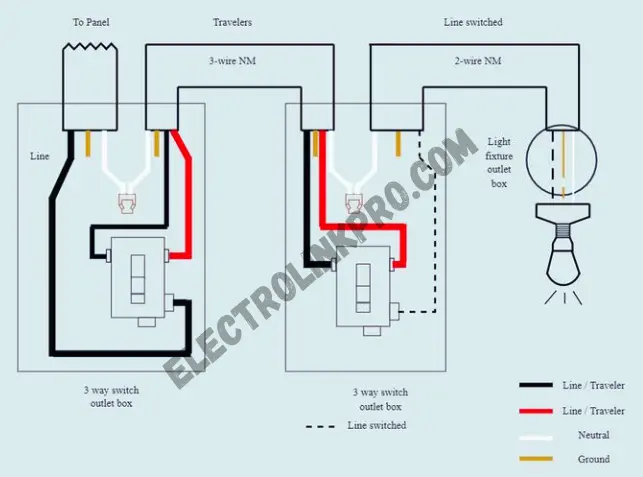
A 3-way switch wiring schematic involves two switches connected via traveler wires. The common terminal on each switch either sends power to the light or interrupts the circuit. Flipping either switch toggles the light on/off.
⚡ Step-by-Step 3-Way Switch Wiring Schematic
Standard 3-Way Switch Wiring Diagram
Here’s the most common 3-way switch wiring schematic:
- Power Source → First Switch → Traveler Wires → Second Switch → Light Fixture
- Black (Hot) Wire → Common terminal on first switch
- Red & Black (Travelers) → Brass terminals on both switches
- White (Neutral) → Directly to the light
- Ground Wires → Connected to all switches and fixture
📝 Step-by-Step Wiring Process
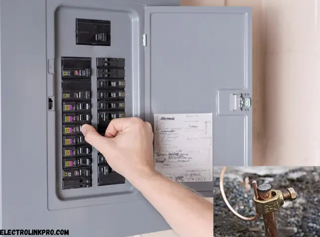
1️⃣ Power Off & Safety Check
- Turn off the circuit breaker supplying power to the switch location.
- Use a voltage tester to confirm no live wires are present.
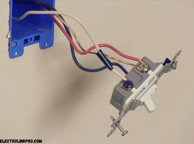
2️⃣ Identify Wires & Terminals
- 3-way switches have 3 screw terminals:
- Common (usually darker screw) – Connects to power or the light.
- Traveler 1 & Traveler 2 (brass screws) – Carry current between switches.
3️⃣ Wiring Configuration (Two Methods)
🔹 Method 1: Power at First Switch
(Power enters the first switch, travelers run to the second switch, and light connects to the second switch.)
- First Switch Box (Power Source):
- Black (Hot) wire → Common terminal of Switch 1.
- White (Neutral) wire → Wire-nutted with other neutrals (not connected to switch).
- Ground (Bare/Green) → Ground terminal of Switch 1.
- Red & Black (Travelers) → Brass terminals (order doesn’t matter).
- Second Switch Box (Light Connection):
- Black wire from light → Common terminal of Switch 2.
- Red & Black (Travelers) → Brass terminals (must match Switch 1).
- White (Neutral) → Connects directly to the light fixture.
- Ground (Bare/Green) → Ground terminal of Switch 2 and light.
🔹 Method 2: Power at Light Fixture
(Power enters the light box, travelers run between switches.)
- Light Fixture Box:
- Black (Hot) wire → Splits to Common terminal of Switch 1 & Switch 2.
- White (Neutral) → Directly to light.
- Ground (Bare/Green) → Light fixture & switch grounds.
- Between Switches (14/3 Cable):
- Red & Black (Travelers) → Brass terminals on both switches.
- White (Neutral) → Not used (cap it off).
2️⃣ Alternate 3-Way Switch Wiring (Power at Light)
If power enters at the light instead of a switch:
- Power Source → Light Fixture → Traveler Wires → Both Switches
- Hot Wire → Splices to the light and one switch
- Travelers → Connect between switches
- Neutral → Directly to the light
3️⃣ Wiring with Multiple Lights
For multiple lights in a 3-way switch wiring schematic, connect them in parallel:
- First Light → Second Light → Third Light (All controlled by two 3-way switches)
🔍 Troubleshooting 3-Way Switch Wiring Schematics
🚨 Common Issues & Fixes
| Problem | Solution |
|---|---|
| Light doesn’t turn on | Check traveler wire connections |
| Only one switch works | Verify common terminal wiring |
| Flickering lights | Tighten all wire connections |
| Circuit breaker trips | Check for short circuits |
🛠 Pro Tips for Reliable Wiring
✔ Use a voltage tester before working
✔ Label wires to avoid confusion
✔ Secure all connections with wire nuts
📊 Comparing 3-Way vs. 4-Way Switch Wiring Schematics
| Feature | 3-Way Switch | 4-Way Switch |
|---|---|---|
| Control Points | 2 locations | 3+ locations |
| Number of Switches | 2 | 3 or more |
| Wiring Complexity | Moderate | High |
A 3-way switch wiring schematic is simpler than a 4-way setup, which requires additional switches for extra control points.
Conclusion:
Understanding and correctly implementing 3-way switch wiring schematics is essential for achieving flexible and convenient lighting control in residential and commercial settings. These setups allow you to operate a single light fixture from two different locations, making them ideal for staircases, hallways, and large rooms.
Key Takeaways
✔ Proper Wiring is Critical – Incorrect connections can lead to malfunctioning switches or electrical hazards.
✔ Follow Standard Schematics – Whether using the “traveler wire” method or alternative configurations, adherence to diagrams ensures reliability.
✔ Safety First – Always turn off power at the circuit breaker before working on electrical installations.
✔ Consult Professionals When Needed – Complex setups, troubleshooting, or upgrades may require a licensed electrician.
When to Seek Professional Help
While DIY enthusiasts can handle basic 3-way switch installations, consider hiring an electrician if:
⚠ The wiring is outdated or damaged.
⚠ You encounter unexpected issues (e.g., no power, flickering lights).
⚠ The circuit involves multiple switches or advanced configurations.
By mastering 3-way switch wiring schematics, you ensure safe, efficient, and convenient lighting control. Always prioritize safety and compliance with local electrical codes.
❓ Frequently Asked Questions (FAQs)
1. What wires are used in a 3-way switch wiring schematic?
A 3-way switch wiring schematic uses hot (black), traveler (red/black), neutral (white), and ground (green/bare) wires.
2. Can I use a 3-way switch as a single-pole switch?
Yes, but you must cap one traveler terminal and use only the common and one brass screw.
3. Why does only one switch work in my 3-way setup?
The common terminal is likely miswired—double-check connections.
4. How do I identify traveler wires in a 3-way switch?
Travelers are connected to brass screws and run between the two switches.
5. Can I add a dimmer to a 3-way switch wiring schematic?
Yes, but use a 3-way compatible dimmer and follow the manufacturer’s wiring guide.
By following this 3-way switch wiring schematic guide, you’ll achieve seamless lighting control! ⚡💡
3-Way Switch Wiring useful links:
🔧 DIY Guide → Family Handyman (Step-by-step photos)
⚡ Smart Switches → Lutron Guide (Wiring dimmers & smart switches)
⚠ Safety → OSHA Electrical (Code compliance tips)
🛠️ Troubleshooting → ElectricianTalk Forum (Pro advice)