Installing or troubleshooting a 3-Way Switch power to light setup is a fundamental skill for any confident DIYer. This specific configuration, where the power source arrives at the light fixture before going to the switches, is incredibly common in modern home construction. While it involves a slightly different approach than other methods, understanding this 3 way switch power to light wiring diagram empowers you to control a single light from two separate locations, like at the top and bottom of a staircase or at either end of a hallway. This guide will provide a deep, step-by-step dive into the components, the process, the theory, and the safety protocols for a successful installation. Let’s illuminate the path to mastering this essential electrical project!
Essential Components and Tools for Your 3-Way Switch Project
Before you touch a single wire, gathering the right components and tools is non-negotiable for both safety and success. A project involving a 3 way switch power to light setup requires specific items that differ slightly from a standard single-pole switch installation. Ensuring you have everything on hand will make the process smooth and efficient.
You will need two special 3 way switch power to light compatible switches. These are distinct from regular switches, featuring three terminal screws: one common (usually a darker color, like black or copper) and two traveler terminals (often brass or silver). You’ll also need 14/2 or 12/2 NM electrical cable (the gauge depends on your circuit amperage; 15-amp circuits use 14/2, 20-amp use 12/2) to run from the power source to the light and from the light to the first switch. Crucially, you will need 14/3 or 12/3 cable to run between the two switches and from the light to the second switch. This 3-wire cable contains black, red, white, and bare copper wires, providing the necessary extra conductor for the travelers. Don’t forget wire connectors (nuts), electrical tape, a voltage tester, and of course, the light fixture itself.
| Component/Tool | Purpose & Specification | Crucial Note |
|---|---|---|
| 3-Way Switches (x2) | To make/break the circuit from two locations. Have one common screw and two traveler screws. | The common terminal is often black or labeled “COM”. |
| 14/2 or 12/2 NM Cable | Carries power from the panel to the light fixture (line). Also used for the switch loop. | 12-gauge for 20A circuits, 14-gauge for 15A circuits. |
| 14/3 or 12/3 NM Cable | Connects the light to the switches and the switches to each other. Carries travelers and neutral. | The red wire is key for separating the traveler conductors. |
| Light Fixture | The device being controlled by the two 3-way switches. | Ensure its wattage is compatible with your bulbs and circuit. |
| Wire Connectors (Nuts) | To securely and safely join copper wires together. | Use the correct size for the number and gauge of wires. |
| Voltage Tester | To confirm power is OFF before working on wires. Non-negotiable for safety. | A non-contact voltage tester is the safest and easiest option. |
| Screwdrivers & Pliers | For securing terminal screws, cutting wire, and bending loops. | Needle-nose pliers are incredibly helpful for precise work. |
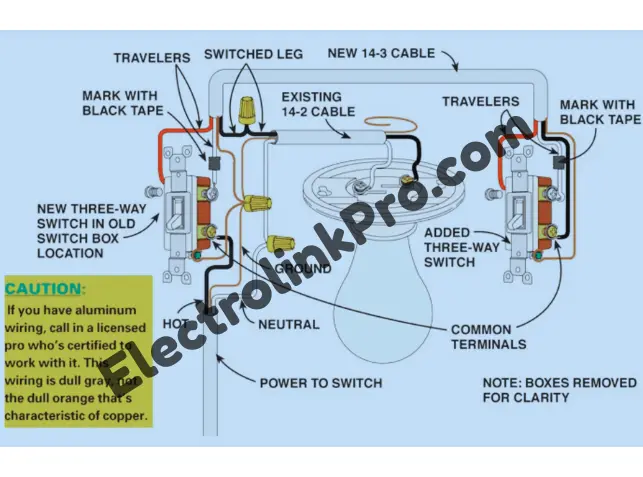
Wiring diagram:
🛠️ Step-by-Step Wiring Instructions: Power to Light
With your tools ready and safety gear on, it’s time to execute the 3 way switch power to light wiring plan. This process methodically connects the power source, the light fixture, and the two switches into a single, functional system. Follow these steps carefully, always double-checking your connections against the 3 way switch power to light diagram.
Step 1: Safety First – Cutting Power at the Breaker
Locate your home’s main service panel and identify the circuit breaker that controls the power to the light fixture’s junction box. Flip the breaker firmly to the OFF position. Use your non-contact voltage tester at the light box to verify that all wires, including the black (hot) wire from the power source, are completely dead. Never assume the breaker is labeled correctly; always test.
Step 2: Wiring the Light Fixture Junction Box
In this 3 way switch power to light configuration, the junction box housing the light fixture becomes the central hub. Here, you will find the 14/2 cable bringing power from the panel (line), and you will be running two other cables out of this box: one 14/3 cable going to the first switch (Switch A) and another 14/3 cable going to the second switch (Switch B).
- Connect the ground wires: Join the bare copper ground from the power-in cable, the ground from the cable to Switch A, the ground from the cable to Switch B, and the ground wire from the light fixture itself with a wire connector. If the box is metal, also connect a pigtail to the ground screw on the box.
- Connect the neutral wires: Join the white wire from the power-in cable, the white wire from the cable to Switch B, and the white (neutral) wire from the light fixture together. Crucially, the white wire in the cable going to Switch A is NOT a neutral in this case; it will be a hot wire. Mark it with black tape to indicate this.
- Connect the hot wires: The black wire from the power-in cable (constant hot) must be connected to the white wire of the 14/3 cable going to Switch A (remember, you taped this black). This is the key to feeding power down to the switch.
- Connect the travelers: The black and red wires from the 14/3 cable going to Switch A will be connected to the black and red wires from the 14/3 cable going to Switch B. These are the traveler wires that will run between the two switches.
Step 3: Wiring Switch A (The First Switch)
At the first switch box, you have a single 14/3 cable coming from the light fixture.
- Connect the ground: Attach the bare copper ground wire to the green ground screw on the 3 way switch power to light compatible switch.
- Identify the common terminal: Locate the darker, common screw on the switch.
- Connect the hot wire: The white wire from the cable (which you marked with black tape at the light) is your “power down” wire. Connect this to the common terminal screw.
- Connect the travelers: The black and red wires from the same cable are the travelers. Connect these to the two brass traveler terminal screws on the switch. It does not matter which traveler goes to which brass screw.
Step 4: Wiring Switch B (The Second Switch)
At the second switch box, you have the other end of the 14/3 cable that runs from the light fixture.
- Connect the ground: Attach the bare copper ground wire to the green ground screw on the second 3 way switch power to light compatible switch.
- Identify the common terminal: Locate the dark common screw on this switch as well.
- Connect the switch leg: The black wire from the 14/3 cable is the “switch leg” that will carry power back to the light to turn it on. Connect this black wire to the common terminal screw on this switch.
- Connect the travelers: Connect the red and the white wires from the cable to the two brass traveler terminals. Again, the order is not important for the travelers.
Step 5: Final Testing and Installation
Once all connections are secure and neatly tucked into their respective boxes, carefully install each 3 way switch power to light device into its box, secure it with screws, and attach the faceplate. Install the light bulb into the fixture. Only then should you return to the breaker panel and restore power. Flip the switches to test their operation. If wired correctly, the light should turn on and off from either location, regardless of the position of the other switch.
🔬 How the “Power to Light” 3-Way Configuration Works
Understanding the theory behind the 3 way switch power to light wiring diagram transforms you from someone who just follows instructions into someone who can troubleshoot and design circuits. The magic of this system lies in the clever use of the “traveler” wires and the internal switching mechanism.
In a 3 way switch power to light setup, the power source feeds the light fixture first. The constant hot wire is then redirected down to the common terminal of the first 3-way switch (Switch A) via the white wire (now re-identified as hot). The purpose of the two switches is to alternate the path of the electrical current along the two traveler wires between them.
Think of the two traveler wires as a bridge that the switches can dynamically reconfigure. The common terminal on each switch is like a pivot point that can connect to either one traveler or the other, depending on the switch’s toggle position. When both switches are in a position where their common terminals are connected to the same traveler wire, the circuit is complete, and the light turns on. If either switch is toggled, it breaks that path by switching the common terminal to the other traveler, interrupting the circuit and turning the light off. This is why you can always change the light’s state from either location—you’re either completing or breaking the continuous path of hot electricity traveling from Switch A, through the travelers, to Switch B, and finally back up to the light.
⚠️ Critical Safety Protocols and Code Compliance
Working with electricity demands the utmost respect for safety. Simply knowing a 3 way switch power to light diagram is not enough; you must adhere to strict safety practices and the National Electrical Code (NEC) to protect yourself, your home, and future occupants.
The single most important rule is to ALWAYS turn off the power at the circuit breaker and then verify it is off with a reliable voltage tester. Never work on live circuits. The NEC has specific requirements for this wiring method. The practice of using the white wire as a hot conductor (as we did from the light to Switch A) is permitted by code, but it must be re-identified with a black tape marker at both ends to indicate it is no longer a neutral. This prevents confusion for anyone who works on the circuit later.
Furthermore, all connections must be made within approved junction boxes, and these boxes must remain accessible (not buried behind drywall). All grounding connections are mandatory for safety, as they provide a path for fault current to trip the breaker and prevent electrocution. If you are unsure about any step or your local code amendments, consulting a licensed electrician is always the best and safest course of action.
🔧 Troubleshooting Common 3-Way Switch Issues
Even with a perfect 3 way switch power to light diagram, things can go wrong. Here’s how to diagnose common problems:
- The light doesn’t turn on at all: This indicates a break in the circuit. Check that the breaker is on. Verify all connections are tight, especially the hot wire at the light box and the common terminal screws on both switches.
- The light only works with one switch: This almost always means the travelers are incorrectly connected. One switch is not able to alternate the path. Go back and verify that the travelers are connected to the brass screws on both switches and that the common wire is on the dark screw.
- The switches don’t seem to follow a logical on/off pattern: This is a classic sign of a miswired common terminal. If the common terminal is accidentally swapped with a traveler, the switches will behave erratically. Double-check that the correct wire is on the common terminal of each switch.
🤔 Alternative 3-Way Wiring Methods
While this article focuses on the 3 way switch power to light method, it’s helpful to know it’s one of several configurations. The other primary method is “power to switch,” where the hot source goes to the common terminal of one switch first, and then the switch leg runs from the common terminal of the second switch to the light. Each method has its place depending on the physical layout of your wiring and the location of the existing power source. Understanding both makes you a more versatile electrician.
Conclusion:
Successfully wiring a 3 way switch power to light system is a rewarding project that enhances the functionality and convenience of your home. By meticulously following the steps—prioritizing safety, understanding the role of each wire (especially the re-identified hot and the travelers), and methodically making connections—you can achieve a professional-grade result. This comprehensive guide has provided the diagrams, the theory, and the practical knowledge needed to tackle this project from start to finish. Remember, the key to mastering the 3 way switch power to light configuration is a careful and patient approach. If your voltage tester ever gives you an unexpected reading, stop and reassess. With this knowledge, you’re now equipped to bring light and control to those tricky two-location spots in your house.
Frequently Asked Questions (FAQ)
1. Can I use a regular switch instead of a 3-way switch in this setup?
No, you cannot. A regular single-pole switch only has two terminals and cannot facilitate the traveler circuit required for control from two locations. You must use special 3 way switch power to light compatible switches, which have three terminals (one common, two travelers).
2. Why does the white wire need black tape on it in the diagram?
In the cable running from the light to the first switch, the white wire is used to carry power down to the switch, making it a hot wire, not a neutral. The National Electrical Code (NEC) requires that any white wire used for a purpose other than a neutral must be re-identified with a different color, typically black tape, at both ends to warn anyone working on the circuit later.
3. What is the purpose of the red wire in the 3-conductor cable?
The red wire is the second “traveler” wire. It provides a second pathway for the electrical current to travel between the two three-way switches. The switches work by alternating the hot current between the black and red traveler wires to either complete or break the circuit to the light.
4. My light flickers or only works sometimes. What’s wrong?
This is almost always caused by a loose wire connection. The most likely culprits are the wires under the common terminal screws or the traveler screws on one of the switches. Turn off the power and check that all terminal screws are tight and that the wire loops are secure.
5. Is it difficult to add a dimmer to this circuit?
Not at all! You simply need to purchase a special 3-way compatible dimmer switch. It will wire into the system in the exact same way as one of the standard 3-way switches. You typically replace only one of the two switches with the dimmer, leaving the other as a standard toggle switch.