Controlling a single light fixture from two separate locations with 3-Way Switch Wiring is a game-changer for home convenience and functionality. This powerful setup relies entirely on a specific 3 way switch wiring diagram. Whether you’re illuminating a long hallway, a grand staircase, or a large room with two entrances, understanding the 3 way switch wiring diagram is the foundational skill. This guide will provide an electrician-level deep dive into every component, configuration, and safety procedure, turning a seemingly complex project into a manageable and rewarding DIY task. We will dissect multiple 3 way switch wiring diagram variations, ensuring you have the confidence to tackle this project correctly and safely.
The Core Components of a 3-Way Switch System ⚙️
Before examining any 3 way switch wiring diagram, you must be able to identify all the necessary parts. A functional system is more than just two switches; it’s an assembly of specific electrical devices and conductors working in unison. Each component has a distinct role, and misunderstanding one can lead to a non-functional circuit or a hazardous situation. We will break down the two primary switch types and the critical wiring that connects them, which is the heart of every 3 way switch wiring diagram.
| Component | Description | Key Identifier |
|---|---|---|
| 3-Way Switches | Specialized switches with three terminal screws, unlike a standard single-pole switch’s two. | Three screw terminals: one common (usually darker, like black or copper) and two traveler terminals (usually brass). |
| Common Terminal | The crucial pivot point on a 3 way switch. It either connects to the power source or the light fixture. | Typically a different color (black) than the other two terminals. It is the heart of the switching action. |
| Traveler Terminals | The two terminals that create the pathway between the two 3 way switches. | Typically brass-colored. The wires connected here are interchangeable between the two terminals. |
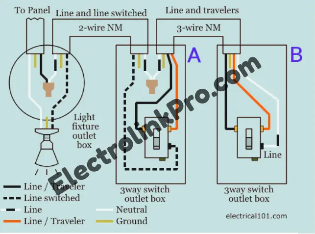
| Traveler Wires | The two conductors that run between the two 3 way switches, carrying the electrical current along the pathway. | Usually black and red insulated wires in the same cable (e.g., 14/3 or 12/3 NM-B cable). |
| Power Source | The origin of the circuit’s electricity, typically from a breaker panel. | The “hot” wire, usually black, that brings power to the first 3 way switch wiring diagram configuration. |
| Light Fixture | The load that the 3 way switch circuit controls. | Connects to the common terminal of the second 3 way switch in a standard setup. |
Tools and materials you needed
Essential Tools for Wiring a 3-Way Switch
Professional-grade tools required for safe and effective electrical work
Voltage Tester
Essential for verifying power is completely off before starting work. This non-contact tool detects live voltage without direct contact with wires.
Wire Strippers
Precision tool for cleanly removing insulation from wires without damaging conductors. Includes calibrated holes for different wire gauges.
Screwdrivers
Set of insulated screwdrivers including flathead and Phillips head. Essential for securing terminal connections on switches and outlets.
Needle-Nose Pliers
Long-nose pliers with insulated handles for bending wires, reaching tight spaces, and positioning wires in electrical boxes.
Flashlight
Hands-free LED headlamp or magnetic work light for illuminating dark electrical boxes and workspace.
Multimeter
Digital multimeter for advanced troubleshooting, continuity testing, and verifying voltage levels in circuits.
Wire Connectors
Assorted wire nuts and connectors for securely joining wires. Various sizes for different wire combinations.
Electrical Tape
High-quality vinyl electrical tape for insulating connections, marking wires, and providing an extra layer of safety.
Electrical Safety Protocols
Always turn off power at the circuit breaker and verify with a voltage tester
Use tools with insulated handles rated for electrical work
Never work on live circuits – even low voltage can be dangerous
Wear safety glasses when cutting wires or working overhead
Step-by-Step Installation Guide for a 3-Way Switch 🛠️
Executing a perfect 3 way switch wiring diagram requires meticulous planning and adherence to safety. This step-by-step guide will walk you through the process from start to finish.
Safety First: Power Off and Verification
- Locate Your Circuit Breaker: Find the correct breaker that controls the circuit you will be working on. Flip it to the OFF position.
- Verify Power is Off: Use a non-contact voltage tester at the switch box and the light fixture. Test between all black and white wires and from black wires to the metal box or ground wire. The tester must not beep or light up.
- Confirm at the Light: Turn the light switch on and off (with the breaker off) to ensure the light does not turn on. This double-check is crucial for safety.
Wiring Implementation: Following the Diagram
- Choose Your Configuration: Determine which 3 way switch wiring diagram you are implementing (power at switch vs. power at light).
- Prepare the Wires: Strip about 3/4 inch of insulation from the end of each wire that will be connected to a terminal.
- Grounding: Always connect all ground wires first. Connect the ground wires from the circuit cables to the green ground screw on each 3 way switch. If in a metal box, also connect a ground pigtail to the box itself.
- Connect Neutrals: Group all white neutral wires together with a wire nut. In boxes where a neutral is not used for the switch itself, simply cap them off and push them to the back of the box.
- Identify the Common Terminal: Find the dark-colored common screw on each 3 way switch. This is your anchor point.
- Make Critical Connections:
- If power enters the first box, connect the source hot wire to the common terminal of the first 3 way switch.
- Connect the traveler wires (black and red from the 3-wire cable) to the two brass screws on the same switch.
- At the second switch, connect the traveler wires to the brass screws.
- Connect the wire going to the light to the common terminal of the second 3 way switch.
- Secure the Switches: Carefully push the switches and wires back into the boxes, ensuring no wires are pinched. Secure the switches with the provided mounting screws.
- Install Faceplate: Attach the decorative wall plate.
Testing and Troubleshooting Your Setup ✅
- Restore Power: Go to your breaker panel and turn the circuit back on.
- Test Operation: Go to your switches and test them. Toggle one switch and see if the light turns on and off. Have a partner help you test from both locations.
- Diagnose Problems: If the light doesn’t work, immediately turn the power back off.
- Light is always on: The most common error is a miswired common terminal. Verify the hot source or the wire to the light is on the common screw, not a traveler screw.
- Only one switch works: The travelers are likely incorrectly connected or there is a break in the traveler wire between the two 3 way switches.
- No power at all: Re-check all connections against your chosen 3 way switch wiring diagram. Ensure the circuit breaker is truly on.
Advanced Concepts and Related Switching Systems 🧠
Once you’ve mastered the standard 3 way switch wiring diagram, you can expand your lighting control systems further. These setups provide even greater flexibility and are built upon the foundational principles of 3-way switching.
Integrating a 4-Way Switch for a Third Location
What if you need to control a light from three, four, or even more locations? You add 4-way switches between the two 3 way switches. A 4 way switch has four terminals and simply reverses the traveler wires. For each additional location beyond two, you add one 4 way switch. The 3 way switch wiring diagram thus expands: the two endpoints are always 3 way switches, and any middle switches are 4 way switches.
Smart 3-Way Switch Solutions
Modern technology offers brilliant solutions that can sometimes simplify the wiring process. Smart switches like Zooz or Inovelli have models designed for 3-way setups but only require a smart switch at one location and a simple, dumb switch at the other. They use wireless communication instead of traditional traveler wires. However, understanding the standard 3 way switch wiring diagram is still essential for providing the necessary line, load, and neutral connections to the primary smart switch.
Comparing with Other Switch Types
It’s important to differentiate a 3 way switch from other common types:
- Single-Pole Switch: Controls a light from one location. Has two terminals (plus ground). It’s a simple on/off switch.
- Dimmer Switch: Can be a single-pole or 3 way switch. It allows you to vary the light intensity. When purchasing a dimmer for a 3-way circuit, you must buy a specific 3 way dimmer switch; a standard single-pole dimmer will not work correctly.
Conclusion:
Successfully wiring a 3-way switch circuit is a highly satisfying electrical project that significantly enhances your home’s functionality. The key to success lies in meticulously studying the correct 3 way switch wiring diagram for your situation, double-checking every connection, and never compromising on safety. By understanding the role of the common terminal, the traveler wires, and the various configuration possibilities, you can diagnose problems and install a reliable system that will serve you for years to come. This knowledge empowers you to tackle more complex setups, like adding 4-way switches or integrating modern smart home technology, putting you in complete control of your home’s lighting
Frequently Asked Questions (FAQs)
1. Can I use a regular switch in a 3-way circuit?
No, a standard single-pole switch lacks the necessary third terminal to operate as part of a 3 way switch system. You must use specialized 3 way switches at both controlling locations for the circuit to function correctly.
2. What is the most common mistake when wiring a 3-way switch?
The most frequent error is misidentifying and miswiring the common terminal. The hot wire (from power) or the wire going to the light must be connected to the common screw (usually darker), not to one of the identical traveler terminals.
3. Do the traveler wires have to be a specific color?
While red and black are standard and highly recommended for clarity in your 3 way switch wiring diagram, the electrical code only specifies that a white wire cannot be used as a hot traveler unless it is re-marked (e.g., with black tape). Using black and red for travelers prevents confusion.
4. Can I install a smart switch in a 3-way setup?
Yes, but you have two options. You can use a traditional 3 way switch wiring diagram with two compatible smart switches, or you can use a specific model of smart switch that only requires itself at one location and uses a provided remote or existing dumb switch at the other location, often simplifying the wiring.
5. Why does my light only work with one switch now?
This almost always indicates a problem with the traveler wires. The common terminals are likely wired correctly, but the connection between the traveler terminals on the two 3 way switches is broken, incorrectly connected, or there is a fault in the traveler wires themselves.