Installing a 3-way switch wiring setup allows you to control a single light from two different locations—perfect for staircases, hallways, or large rooms. This guide provides a detailed 3-way switch wiring diagram, step-by-step instructions, and expert tips to ensure a safe and efficient installation.
Whether you’re a DIY enthusiast or an electrician, mastering 3-way switch wiring is essential for flexible lighting control. Let’s dive into the wiring configurations, tools needed, and common mistakes to avoid.
🛠 Tools & Materials Needed for 3-Way Switch Wiring
Before starting, gather these essentials:
| Tool/Material | Purpose |
|---|---|
| 3-way switches (2) | Control light from two locations |
| 14/3 or 12/3 NM cable | Carries traveler wires between switches |
| Electrical tape | Insulate wire connections |
| Wire stripper | Strip insulation from wires |
| Voltage tester | Check for live wires |
| Screwdriver | Secure switch terminals |
🔹 Pro Tip: Always turn off the power at the breaker before working on 3-way switch wiring to prevent electrical hazards.
3-Way Switch Wiring Diagram & Step-by-Step Installation
Here is complete wiring diagram for a 3 way switch
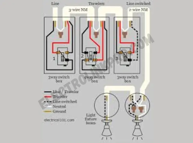
🔧 Detailed 3-Way Switch Wiring Steps
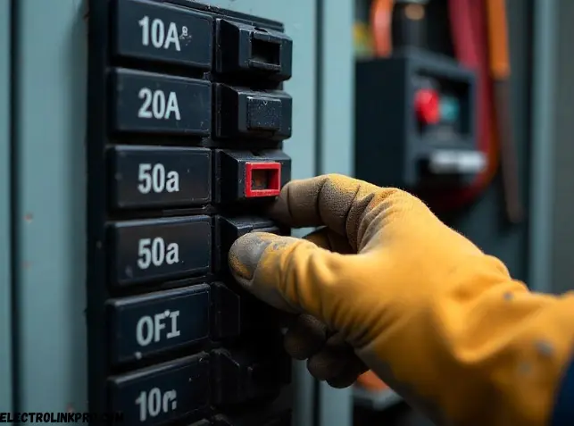
Turn Off Power at the Breaker
🔹 Why it’s critical: Working on live wires can cause severe electrical shocks or fires.
🔹 How to do it:
- Locate your home’s main electrical panel.
- Identify the correct circuit breaker controlling the switches/light.
- Flip the breaker to the OFF position.
- Double-check with a non-contact voltage tester to confirm power is off at the switch box.
Run 14/3 or 12/3 Cable Between Switches and Light
🔹 Why 3-conductor cable? A 3-way switch wiring setup requires:
- Black (Hot) – Carries power
- Red (Traveler) – Connects switches
- White (Neutral/Traveler) – Completes the circuit (may be re-marked as a traveler)
- Bare/Ground (Safety ground) – Prevents electrical faults
🔹 Installation Tips: - Use Romex NM-B cable for in-wall runs.
- Secure cables with cable staples every 4-6 feet.
- Leave 6-8 inches of extra wire in each box for connections.
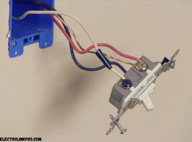
Connect the Common Terminal (Dark Screw) to Power at the First Switch
🔹 Identifying the common terminal:
- The dark-colored screw (usually black or copper) is the common terminal.
- The two brass screws are for the traveler wires.
🔹 Wiring the first switch: - Attach the LINE (hot) wire (black) from the power source to the common terminal.
- Connect the red and black traveler wires to the brass screws (order doesn’t matter).
- Cap the neutral (white) wire with a wire nut if not used.
Link Traveler Wires (Red & Black) Between Switches
🔹 How traveler wires work:
- These wires allow communication between the two switches.
- They carry current back and forth but don’t connect to the light directly.
🔹 Proper connections: - At the first switch, attach the red and black travelers to the brass screws.
- At the second switch, connect the same red and black wires to the brass screws.
- No need to match colors—travelers are interchangeable.
Attach the Second Switch’s Common Terminal to the Light Fixture
🔹 Completing the circuit:
- The common terminal (dark screw) on the second switch sends power to the light.
- Connect the black wire (LOAD) from the light fixture to this terminal.
- If using a neutral wire (white), connect it to the fixture’s neutral terminal.
Secure Ground Wires to Switches & Box
🔹 Grounding for safety:
- Twist all bare copper ground wires together in each box.
- Attach a pigtail ground wire to each switch’s green screw.
- Secure the ground wire to the metal junction box (if applicable).
Test the Circuit Before Closing Up
🔹 Final verification steps:
- Turn the breaker back ON.
- Test both switches—the light should turn on/off from either location.
- If the light doesn’t work:
- Check for loose connections.
- Verify traveler wire continuity with a multimeter.
- Ensure the common terminal is correctly wired.
🔹 Pro Tip: Use a circuit tester to confirm proper wiring before reinstalling switches.
🔌 Quick Reference Table: 3-Way Switch Wiring Connections
| Component | Wire Color | Terminal | Function |
|---|---|---|---|
| First Switch | Black (Hot) | Common (Dark Screw) | Receives power |
| Traveler Wires | Red & Black | Brass Screws | Links switches |
| Second Switch | Black (Load) | Common (Dark Screw) | Sends power to light |
| Ground Wires | Bare Copper | Green Screw | Safety grounding |
🔍 Common 3-Way Switch Wiring Mistakes & Fixes
❌ Incorrect Traveler Wire Connections
- Issue: Lights don’t turn on/off properly.
- Fix: Ensure red & black traveler wires are connected to brass screws on both switches.
❌ Mixed-Up Common Terminal
- Issue: One switch works, but the other doesn’t.
- Fix: Verify the common terminal (dark screw) is correctly linked to power or light.
❌ Loose Wire Connections
- Issue: Intermittent light operation.
- Fix: Tighten all screws and use wire nuts for secure connections.
🔹 Pro Tip: Label wires before disconnecting old switches to avoid confusion.
🔄 Alternative 3-Way Switch Wiring Methods
1. Power at Light Fixture
- Hot wire connects to the light first.
- Travelers run between switches.
2. Power at Switch Box
- Hot wire enters the first switch.
- Travelers run to the second switch.
🔹 Best Practice: Choose the method that minimizes wire runs for efficiency.
✅ Testing & Troubleshooting 3-Way Switch Wiring
- Use a voltage tester to confirm power is off.
- Check all connections for tightness.
- Verify traveler wire continuity with a multimeter.
- Test switch operation before finalizing installation.
🔹 Safety Reminder: Never work on live circuits—always double-check with a tester.
🏁 Conclusion: Mastering 3-Way Switch Wiring
Understanding 3-way switch wiring is crucial for flexible lighting control in homes and offices. By following the correct 3-way switch wiring diagram, avoiding common mistakes, and testing thoroughly, you can ensure a safe and functional setup.
📌 Need more help? Consult a licensed electrician for complex installations!
❓ FAQs About 3-Way Switch Wiring
1. Can I use a 2-wire cable for 3-way switch wiring?
No, 3-way switch wiring requires a 3-wire cable (14/3 or 12/3) to carry traveler wires between switches.
2. Why does only one switch work in my 3-way setup?
The common terminal is likely miswired—check connections at both switches.
3. Can I install a dimmer in a 3-way switch circuit?
Yes, but you’ll need a 3-way compatible dimmer switch for proper functionality.
4. What’s the difference between a 3-way and 4-way switch?
A 3-way switch wiring setup uses two switches, while a 4-way switch adds more control points (3+ switches).
5. How do I identify the common wire in a 3-way switch?
The common terminal is usually the dark screw on the switch.
Here are some official & authoritative resources for 3-way switch wiring:
🔧 Electrical Codes & Standards
- NFPA 70 (NEC) – www.nfpa.org/70 (National Electrical Code)
- OSHA Electrical Safety – www.osha.gov/electrical
📘 Wiring Guides & Diagrams
- UL Solutions – www.ul.com (Safety-certified products)
- Energy.gov (DoE) – www.energy.gov (Home electrical efficiency)
🛠 DIY & Professional Help
- International Association of Electrical Inspectors (IAEI) – www.iaei.org
- Electrician Forums (Mike Holt) – forums.mikeholt.com